Feature Manual
The features of SpinDrops are described here in four sections: Menus, Windows, Preferences, and Keyboard Shortcuts.
Menus
View Menu
The menu opens some windows to view the experiment, and over the display size. It also has some control over how the DROPS Representation is displayed.
List Prod. Ops…
This menu opens the List List Prod. Ops Window.
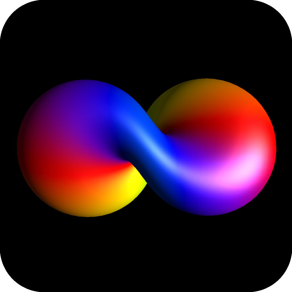
Phase Color Ref…
This menu opens the Phase Color Ref Window.
Density Operator…
This menu opens the Density Operator Window.
Hamiltonian…
This menu opens the Hamiltonian Window.
Eff. Hamiltonian…
This menu opens the Effective Hamiltonian Window.
Propagator…
This menu opens the Propagator Window.

Separation
The menu lets you choose which of the Separation Types is used for the DROPS Display.
These are: - Standard - Standard Plane - Coh. Order |p| - Coh. Order p - Rank j, - j, |p|, - j, p
Zoom
The GUI can be made larger or smaller according to the entries in this menu. Be careful not to make it too small!
Windows
Preferences Window
The menu selection opens the Preferences Window. It is the place to set user-configurable Preferences.

Fig. 34 Preferences Window
The current Preferences schema is displayed at the top of the Preferences Window. Selecting an entry from the drop-down menu changes to another schema. Changing preferences settings only changes the setting within the current schema.
The Reset Settings button will reset any customization in the current schema back to the values of the Default Schema. If the Default Schema is selected, then the settings will be reset to their “factory defaults” – SpinDrops’ default settings.
The Remove Schema button will delete the current schema.
To create a new schema, enter a New Name for your schema in the corresponding text box, and click Create.
Note
It may be easier to use Project to store different combinations of settings rather than Schemas, depending on what you are trying to do.
System Parameters Window
The menu selection opens the System Parameters Window.

Fig. 35 System Parameter Editor
Initial State Graphical Edit Window
The menu selection opens this window.

Fig. 36 Graphical Initial State Editor
Initial State Textual Edit Window
The menu selection opens this window.

Fig. 37 Textual Initial State Editor
Product operators can be specified here in a syntax we call
Plain Text Operator Notation which looks like \(I_{1x}I_{2z}\), or by using raw matrix
expressions. The raw matrix expressions can only specify matrices of
fixed size, so will only be applicable to a particular sized spin
system. The syntax for the matrix expressions is somewhat
octave/matlab-like. For example, \(Ix\) would be specified as
[0,0.5;0.5,0] - individual values are separated by commas and
rows are separated by semi-colons. More details can be found here:
https://github.com/marcel-goldschen-ohm/EigenLab#defining-matrices-within-parsed-expressions .
Operator Inspector Window
The menu selection opens this window. It can be used to inspect and
explore operator expressions. The functions rho() and
t_() can be used to query information from the simulation.

Fig. 38 Operator Inspector
EigenLab Cheat Sheet
The EigenLab language in short:
Defining matrices:
[1,2;3,4]
ones(N)      ones(M,N)
zeros(N)     zeros(M,N)
eye(N)       eye(M,N)
zeros(N)     zeros(M,N)
rand(N)      rand(M,N)
Element-wise operations:
C = A - B
C = A + B
C = A .* B
C = A ./ B
C = A ^ b   (b scalar)

abs(A) = [abs(A(1,1) abs(A(1,2)) ... ; abs(A(2,1)) abs(A(2,2)) ... ; ...]
sqrt(A)=  "
exp(A) =  "
log(A) =  "
log10(A)= "
sin(A) =  "
cos(A) =  "
tan(A) =  "
asin(A)=  "
acos(A)=  "
Matrix operations:
C = A * B
trace(A)
norm(A)
size(A,0)  size(A,1) // size of dim 0/1
mean(A)    mean(A,0)  mean(A,1) // mean along dim 0/1
sum(A)     sum(A,0)   sum(A,1)  // sum along dim 0/1
prod(A)    prod(A,0)  prod(A,1) // prod along dim 0/1
kron(A,B)
transpose(A)
conjugate(A)
adjoint(A)
normalize(A)
expm(A)
logm(A)
Special functions and matrices to probe the simulation
Id          // Identity matrix for current system
I1x,I1y,..  // Various basis elements, see PTON
rho()       // return the current density matrix
rho(1.1)    // return the density matrix at time t=1.1 s
t_()        // return the current time of the time slider
t_(1)       // return the time at the end of the 1st sequence element
rho(t_(1))  // return the density matrix at the end of the 1st sequence element
Tabular Pulse Sequence Editor
The menu selection opens this window. It provides an interface for editing simple pulse sequences.

Fig. 39 Simple Sequence Editor
Pulse Sequence Explorer Window
The menu selection opens this window.

Fig. 40 Pulse Sequence Explorer
Show Raw Sequence
This checkbox in the Pulse Sequence Explorer Window enables the raw editing of the JSON that defines table-type sequences. Normally these sequences can be edited using the table-editor.

Fig. 41 Raw JSON sequence view
Apply to Simulation
This checkbox in the Pulse Sequence Explorer Window enables continuous update of the simulation as the sequence text is edited.
Pulse Sequence Optimizer Window
The menu selection opens this window.

Fig. 42 Pulse Optimizer
This window optimizes the pulse sequence according to a cost function - which is some distance measurement between the final simulation state (the Density Operator at the end of the simulation time) and a “target state”. The target state can be set in the text box Target. More information about sequence optimization and this tool can be found under Sequence Optimizer.
Pulse Explorer Window
The menu selection opens this window.

Fig. 43 Pulse Explorer Window
Todo
finish description
Phase Color Ref Window
The menu selection opens this window.
List Prod. Ops Window
The menu selection opens this window . A list of the current Density Operator factored into the Cartesian Product Operator basis is displayed by default. Right-clicking (or long-clicking) on the window brings up a list of other possible bases by which the Density Operator can be factored. This list can be hidden by closing the window.
View Operator Windows
There are a number of Operator viewing windows. They all have the same behavior, but display different operators for different aspects of the experiment.
The set of operators that can be displayed are:
the Density Operator
the Hamiltonian
the Effective Hamiltonian
the (effective) Propagator
the (current) Propagator
Any of these Operators can be viewed in a number of different ways. There are three basic views of an Operator in SpinDrops: 1) the DROPS Representation, 2) raw matrices, and 3) basis decomposition.
Right-clicking (or long-clicking) on an Operator Viewing window brings up a menu that selects the viewing mode for the window. This presents different ways to view the operator:

Fig. 44 Operator View Menu
Colored Matrix Elements
This draws the Operator as a matrix. It uses the matrix elements’ phase to color the background of the entry, and it does NOT show any numerical values.

Fig. 45 ‘Colored Matrix Elements’ view
Color Matrix with Values
This shows the Operator as a matrix. It uses the matrix elements’ phase to color the background of the entry, and draws the numerical value of the entries in a contrasting color.

Fig. 46 ‘Color Matrix with Values’ view
Matrix Monochrome
This shows the Operator as a numeric matrix, using the Foreground and Background colors for the fore- and background, respectively.

Fig. 47 ‘Matrix Monochrome’ view
Matrix Values Only
This shows the Operator as a numeric matrix, using the phase of the entries to choose the color to draw the entry. This is similar to the Color Matrix with Values, but instead of using the phase color for the background, it is used for the text itself.

Fig. 48 ‘Matrix Values Only’ view
Eigen Decomposition
This view of an operator presents an eigen value/eigen vector decomposition of the operator’s matrix representation. The view is non-square, with the left-most column showing the eigenvalues, and the “matrix part” displaying the eigenvectors as columns of the matrix.
The eigenvalues are first sorted by amplitude and then phase (if the amplitudes are the same, then the phase determines the order). The remaining \(N\) columns of the matrix are the eigenvectors. If there are non-unique eigenvalues, the eigenvalues will be sorted by the entries of the eigenvectors. The eigen decomposition of some, particularly (nearly-) unitary matrices is not necessarily numerically stable, so small changes in, for example, a time duration may change the display suddenly.

Fig. 49 ‘Eigen Decomposition’ view
DROPS
This shows the selected Operator using the currently selected DROPS Representation. This display is explained in detail in the section DROPS Representation.

Fig. 50 ‘DROPS’ view
List Basis Elements
This mode decomposes the Operator into the selected basis. There are a number of common bases available:

Fig. 51 Basis selection menu
Basis name |
Product Elements |
|
|---|---|---|
Cartesian {x,y,z,e} |
\(I_x,I_y,I_z,I_e\) |
See Cartesian Basis. |
Semi-Cart. A {+,-,z,e} |
\(I^+,I^-,I_z,I_e\) |
See Semi-Cartesian Basis. |
Semi-Cart. A, Homog. {+,-,z,e} |
\(I^+,I^-,I_z,I_e\) |
See Semi-Cartesian Basis. |
Semi-Cart. B {x,y,α,β} |
\(I_x,I_y,I_\alpha,I_\beta\) |
See Semi-Cartesian Basis. |
Semi-Cart. B, Homog. {x,y,α,β} |
\(I_x,I_y,I_\alpha,I_\beta\) |
See Semi-Cartesian Basis. |
Single Elem. {+,-,α,β} |
\(I^+,I^-,I_\alpha,I_\beta\) |
See Single Element Basis. |
LISA Basis |
See LISA Basis. |
|
Qbit Basis |
\(|0\rangle\langle{0}|,|0\rangle\langle{1}|,|1\rangle\langle{0}|,|1\rangle\langle{1}|\) |
See Qbit Basis. |
Cartesian Basis
The Cartesian basis elements are defined to be generators of rotation such that, ie \(e^{-i \frac{\pi}{2} I_y} I_z e^{i \frac{\pi}{2} I_y} = I_x\). The scalar product here is defined as \(\langle A_i | A_j \rangle = Tr(A_i^\dagger A_j)\), and the norm \(||A_i|| = \sqrt{\langle A_i | A_i \rangle}\).
Thus, while the Cartesian product operator basis is orthogonal, and all basis elements have the same norm, it is generally not normalized in the sense of \(||A_i|| = 1\) (except specifically in the 2-spin case). For 1-, 2-, and 3- spin systems, the norms of the Cartesian product operator basis elements, \(B_r\), are
\(B_r\) |
\(|| B_r ||\) |
|
|---|---|---|
1 spin |
\(I_x\) |
\(\frac{1}{\sqrt 2}\) |
2 spin |
\(I_{1x}\) |
\(1\) |
2 spin |
\(2I_{1x}I_{2y}\) |
\(1\) |
3 spin |
\(I_{1x}\) |
\(\sqrt 2\) |
3 spin |
\(2I_{1x}I_{2y}\) |
\(\sqrt 2\) |
3 spin |
\(4I_{1x}I_{2y}I_{3z}\) |
\(\sqrt 2\) |
N spin |
\(2^{q-1}\prod^q I_d \quad d \in \{x,y,z\}\) |
\(2^{\frac{N}{2}-1}\) |
Spherical Tensor Basis
Single Element Basis
Semi-Cartesian Basis
The List Basis Elements offers four different Semi-Cartesian Basis decompositions. These consist of two different selections of generating operators (A and B), each of which can have different scalings of the individual basis elements (Regular and Homogenous scalings).
As a reminder, the one spin basis elements in matrix form are shown in Table Table 1.
\[\begin{split}I_x = \frac{1}{2} \begin{bmatrix}
0 & 1 \\
1 & 0
\end{bmatrix}\end{split}\]
|
\[\begin{split}I_y = \frac{1}{2} \begin{bmatrix}
0 & -i \\
i & 0
\end{bmatrix}\end{split}\]
|
\[\begin{split}I_z = \frac{1}{2} \begin{bmatrix}
1 & 0 \\
0 & -1
\end{bmatrix}\end{split}\]
|
\[\begin{split}I_e = \frac{1}{2} \begin{bmatrix}
1 & 0 \\
0 & 1
\end{bmatrix}\end{split}\]
|
|---|---|---|---|
\[ \begin{align}\begin{aligned}\begin{split}I^+ = I_x + iI_y = \\\end{split}\\\begin{split}\begin{bmatrix}
0 & 1 \\
0 & 0
\end{bmatrix}\end{split}\end{aligned}\end{align} \]
|
\[ \begin{align}\begin{aligned}\begin{split}I^- = I_x - iI_y = \\\end{split}\\\begin{split}\begin{bmatrix}
0 & 0 \\
1 & 0
\end{bmatrix}\end{split}\end{aligned}\end{align} \]
|
\[ \begin{align}\begin{aligned}\begin{split}I^\alpha = I_e + I_z = \\\end{split}\\\begin{split}\begin{bmatrix}
1 & 0 \\
0 & 0
\end{bmatrix}\end{split}\end{aligned}\end{align} \]
|
\[ \begin{align}\begin{aligned}\begin{split}I^\beta = I_e - I_z = \\\end{split}\\\begin{split}\begin{bmatrix}
0 & 0 \\
0 & 1
\end{bmatrix}\end{split}\end{aligned}\end{align} \]
|
The A-type Semi-Cartesian basis is composed of product operators created from the elements \(I^+\), \(I^-\), \(I_z\), and \(I_e\) (\(\frac{1}{2}E\)).
The B-type Semi-Cartesian basis is composed of product operators generated from the elements \(I_x\), \(I_y\), \(I^\alpha\), and \(I^\beta\).
The Regular (non-Homogenous) element scaling simply defines the elements of the basis as the unscaled products of the terms from Table Table 1. For a concrete example, take a three-spin-1/2 operator in the A-type Semi-Cartesian basis \(I_{1}^{+}I_{2}^{-}I_{3z}\), defined as \(I^+ \otimes I^- \otimes I_z\). The norm of this operator (\(|I_{1}^{+}I_{2}^{-}I_{3z}|\)) is \(xxx\), but in the Homogenous basis, it is rescaled so that it only represents a direction, so to say, and has the same norm as, say, \(I_{1x}\): \(xxx\).
A basis element \(B\) is written below by defining \(q\) as the number of \(x,y,z\) terms, and \(q'\) as the number of single element terms (\(+,-,\alpha,\beta\)) :
Defining
the regular scaling of the elements B is
and the Homogenous scaling is
This table provides some more concrete examples:
Qbit Basis
The basis elements are actually the same as the Single Element Basis elements, but use naming familiar to the Quantum Information community. The elements are named using bra-ket notation, in the form of a ket followed by a bra. The wave function name contained within the bra-kets is a bit string identifying the state. For example, a two-level system has the pure states \(\lvert0\rangle\) and \(\lvert1\rangle\), a four level system has pure states \(\lvert00\rangle\), \(\lvert01\rangle\), \(\lvert10\rangle\), and \(\lvert11\rangle\), and so on for each additional quantum bit.
The operators of the density operator basis are then composed by ket-bra combinations of these states, ie for a two level system: \(\lvert1\rangle\langle{1}\rvert\). Each operator basis element in matrix form has exactly one non-zero (unitary) entry, which can be though of also as the matrix element at the (row,column) corresponding to the (ket,bra) pair: \(\lvert1\rangle\langle{0}\rvert\) is a 2x2 matrix with a \(1\) at (row 1, column 0) and zeros elsewhere. For larger systems, the addresses can be interpreted as binary numbers for the (row,column): \(\lvert11\rangle\langle{10}\rvert\) is a 4x4 matrix with a \(1\) at (row \(11b\), column \(10b\)), ie (row 3, column 2):
Operators from the Qbit Basis can also be used in defining the initial
state and in sequence definitions by using the associated PTON
notation, which in this example would
be |11><10|.
Density Operator Window
The menu selection opens this window. This is one of the View Operator Windows, it shows the Density Operator: \(\rho(T)\) where \(T\) is the current time.
Hamiltonian Window
The menu selection opens this window. This is one of the View Operator Windows, it shows the Hamiltonian Operator: \(\frac{\mathcal{H}(T)}{2\pi}\) where \(T\) is the current time. It has the same features as all View Operator Windows. An expression for the current Hamiltonian can be seen by enabling the Show Details preference setting.
Effective Hamiltonian Window
The menu selection opens this window. This is one of the View Operator Windows, it shows the Effective Hamiltonian Operator, \(\mathcal{H_{\text{eff}}}(T)\) where \(T\) is the current time.
The Effective Hamiltonian is defined as the time-constant Hamiltonian that would produce the current propagation until the current time, \(T\). It is closely related to the propagator \(U(T)\) displayed in the Propagator Window, and defined as
Using the matrix \(log()\) in this case can sometimes produce unexpected results. There is not necessarily a unique solution B that satisfies B = log(A); for a given A, also C = log(A) can be true, where B neq C. Due to the way log(A) is calculated, small changes to the argument, ie A+epsilon can produce large sudden changes is the value of log(A), as the solver jumps between different smoothly connected solutions B’ and C’.
Propagator Window
The menu selection opens this window. This is one of the View Operator Windows, it shows the Propagator as an Operator, \(U(T)\), where \(T\) is the current time.
\(U(T)\) is defined in terms of an experiment consisting of n+1 :math:time periods having constant Hamiltonians for each per \(\mathcal{H_0} .. \mathcal{H_n}\), each of duration :math:\(\tau_k\), and defining the start of a period \(t_0 = :math:0, t_{k|k>0} = \sum_{n=0}^{k-1} \tau_n\), the propagator of a :math:period \(U_k = exp(-i \mathcal{H_k} \tau_k)\), and the index :math:\(m\) of the period in which the time \(T\) can be :math:found, \(m \text{ s.t. } t_m < T < t_{m+1}\) .
Elem. Propagator Window
The menu selection opens this window. This is one of the View Operator Windows, it shows the propagator for the current time segment as an Operator, \(U_k([T_k,T_{k+1}])\), where \(T_k\) is the beginning of the current sequence element \(k\) containing \(T\).
Notice that this is a different propagator from the one defined in the Propagator Window. This propagator is only for a single, entire pulse sequence element, wherease the Propagator Window shows the effective propagator from the beginning of the sequence until the current time point.
This is simply \(U_k = exp(-i \mathcal{H_k} \tau_k)\), where \(\mathcal{H_k}\) is the Hamiltonian for the current time period.
About Window
The about window displays information about the current version of SpinDrops, the environment that SpinDrops is currently running on, some current low-level settings, and, on desktop versions, a short summary of the Keyboard Shortcuts.
Preferences
This section details the user-configurable settings of SpinDrops. These settings can be controlled from the Preferences Window which can be opened from the menu .
DROPS
Apply RX Phase
When this option is enabled, the Density Operator is shown in the DROPS Display with the receiver phase applied. For example, if the sequence sets the receiver phase to 180°, and the current Density Operator is \(I_{1x}\), then the DROPS display will show the Operator \(e^{-i \pi} I_{1x}\), ie \(-I_{1x}\), the phase of the receiver will also be indicated by the color of the “coil” icon and label in the top-right corner of the DROPS display. When the “coil” icon is not present, the receiver phase is \(0°\).
Fig. 52 and Fig. 53 show the same sequence. The sequence has two sub-sequences with different receiver phases. The first sub-sequence is a 90°x pulse followed by an acquisition with the receiver set to x-phase, the second sub-sequence is a 90°(-x) pulse followed by an acquisition followed by an acquisition with the receiver set to -x phase. Enabling the Apply RX Phase option shows the sub-sequence as the receiver would see it, as in Fig. 53, the magnetization appears to be in the -y direction. An important point to note here is that the receiver phase does not change the shapes of the droplets, it only changes the colors.

Fig. 52 Sequence with two different RX Phases, Apply RX Phase disabled

Fig. 53 Sequence with two different RX Phases, Apply RX Phase enabled
This setting does not affect how the signal summation is performed – in the panel on the right, the summation of the sub-experiments is always performed by the pulse sequence’s receiver phase definition.
Extra Droplet Labels
This adds text labels to identify the non-Magnetization Droplets, additionally, droplets that are separated will have labels indicating their rank \(j\) and coherence(s) \(p\).
Hide Couplings
By default, the J couplings between spins are indicated by lines. To remove these lines, select Hide Couplings.
To show the lines again, uncheck Hide Couplings.
Magnetization Droplets
This enables drawing Droplets to represent the magnetization components of the density operator. When it is disabled, no droplet will be drawn for the magnetization. When Magnetization Vectors is enabled, the Magnetization Droplets are drawn transparently, so that the vectors can be seen. But when the Vectors are not drawn, the Magnetization Droplets are drawn opaquely, like the other Droplets.
Magnetization Only
Hide all droplets that are not magnetization droplets. This is useful if for some reason you want to hide the complications of coupling.
Magnetization Vectors
This enables drawing Bloch Vectors at the spin positions representing the magnetization of the respective spin. If Magnetization Droplets are also enabled, those droplets will be drawn semi-transparently so that the Bloch Vectors can be seen.
Show Droplet Labels
This enables the basic Droplet labels on spins I1, I2 and I3. It does not enable the other droplet labels, which are controlled by Extra Droplet Labels.
Show Id Droplet
This enables drawing of the Identity Droplet, which is a sphere indicating the magnitude and phase of the Identity part of the Operator.
Colors
Background
The background color of the SpinDrops App, internally this is stored as a four-valued RGBA color. The alpha channel can be set to transparent to affect the background of saved movie frames and saved DROPS images.
Foreground
The foreground color of the SpinDrops App, internally this is stored as a four-valued RGBA color. This is the color that text and the coupling bars are drawn in. Ideally it should offer some contrast when compared with the Background color.
General
Grid Layout
This setting controls the layout of multiple frames, multiple frames occur when the experiment has several concurrent parts, e.g., for phase cycling. When Grid Layout is enabled, the layout will attempt to lay-out the frames in a square grid. If Grid Layout is not enabled, the frames will be laid out in either rows or columns, depending on the value of the Row Layout setting.
Row Layout
This setting interacts with the Grid Layout setting to determine how multi-frame experiments are displayed. If Grid Layout is disabled, this setting controls whether the frames are laid-out in rows or columns.
Show Axes
This enables the drawing of a 3D Axes glyph to orient the viewer in 3D space.
‘Show Axes’ Enabled
|
‘Show Axes’ Disabled
|


Show Details
When this option is enabled, extra information about the current sequence and simulation will be drawn in the top right corner of the screen. It includes the current preferences scheme, the current sequence name, the current Hamiltonian and the textual representation of the current Initial State.
Show Pointer
By choosing the option Show Pointer, touch points can be highlighted by orange circles.
This option is particularly useful when the SpinDrops display is projected on a big screen. For example during a lecture, a touch point can be used as a pointer to focus attention on specific items on the screen. This option can also help to explain the effects of touch gestures when the position of the fingers cannot be seen on the big screen, see example below.
Simulation
Ideal Pulses
This setting affects the Hamiltonian that is used to calculate pulse evolution. When it is enabled, the Hamiltonian during pulses will not contain \(H_{\text{free}}\) (ie chemical shift) terms.
Keyboard Shortcuts
The Desktop and Web versions of SpinDrops have a number of keyboard shortcuts to make navigating the UI easier
q e        - Rotate (counter-)clockwise
w s        - Roll forward/backward
a d        - Twist left/right
+ -        - Zoom in/out
< >        - Jump to next/previous sequence element
[ ]        - Jump to begin/end of sequence
shift-.
shift-,    - Jump to next/previous sequence element
* /        - Simulate faster/slower
arrow keys - Slide view around the frame
[space]    - Start/stop simulation
1,2,3      - Change to 1-,2-, or 3-spin systems
4          - Change to 3-spin systems in chain layout
r          - Toggle simulation repeat mode
D          - Open the Density Operator window
E          - Open the Eff. Hamiltonian window
H          - Open the Hamiltonian window
U          - Open the Propagator window
R          - Set a random initial density operator
b          - Load a random sequence
n          - Cycle through separation modes
ctrl-i     - Open the Info window
ctrl-,     - Open the Preferences window
ctrl-.     - Open the Spin System parameter editor
ctrl-d     - Toggle display of details box
ctrl-e     - Open the Sequence Editor
ctrl-f     - Toggle the finger/touch circles
ctrl-F     - Toggle Fullscreen mode
ctrl-l     - Open the list product operator window
ctrl-o     - Open the pton initial operator window
ctrl-O     - Open the graphical operator edit window