Tutorial
How to Use SpinDrops
A typical approach to see the spin dynamics of a pulse sequence:
Select a spin system and its parameters (offset frequencies and coupling constants).
Choose the initial state of the spin system (e.g. z magnetization of spin I1).
Pick a pulse sequence (e.g. a 90° pulse followed by a delay).
Run the pulse sequence by touching the play icon ( ► ) to see the resulting time evolution in the DROPS display.
The following tutorial provides a more detailed tour.
The Start Screen
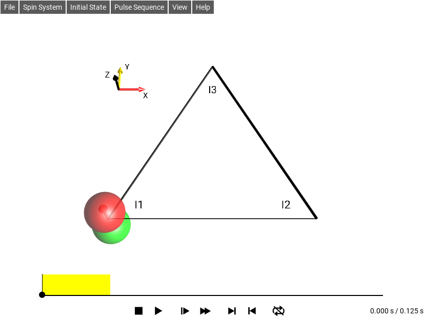
Fig. 2 Default SpinDrops Screen
The menu bar is in the upper left.
The DROPS display is the 3D drawing in the center of the screen.
The simulation control panel is at the bottom of the screen.
The pulse sequence (experiment) appears above the control panel with an indicator of the current simulation time.
Selecting a Spin System Layout
By default, the menu option is selected. It is the most general layout for systems involving up to three coupled spins. However, particularly for applications involving only a single spin, two spins, or a three spin chain with no coupling between the first and the third spin, the display can be simplified by selecting one of the options , , or .
1-Spin 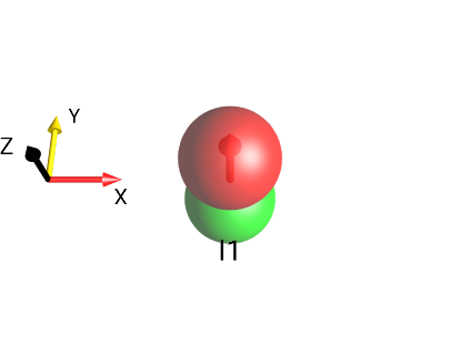
Fig. 3 \(I_{1z}\)¶ |
2-Spin 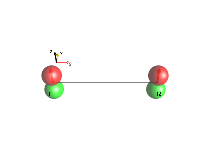
Fig. 4 \(I_{1z}+I_{2z}\)¶ |
3-Spin Chain 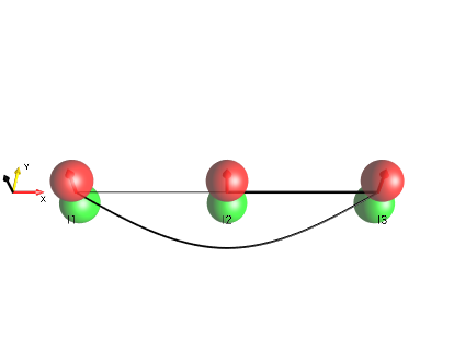
Fig. 5 \(I_{1z}+I_{2z}+I_{3z}\)¶ |
3-Spin Triangle 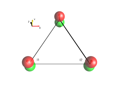
Fig. 6 \(I_{1z}+I_{2z}+I_{3z}\)¶ |
Setting Spin System Parameters
The spin system parameters (offset frequencies ν and J couplings) can be inspected and modified in a control panel that can be opened in the menu . The editor can be seen in Fig. 7.
The offset frequencies ν1, ν2, ν3 and the coupling constants J12, J13, J23 can be set using the sliders. The default range for these parameters is ± 2 Hz. This ensures that the spin dynamics are fluent for typical frame rates of mobile devices. The sliders adjust these values in steps of 0.1 Hz. This makes it easier to set a slider e.g. to a value of exactly 0 Hz. It is also possible to manually enter arbitrary parameter values in the text box above the respective slider.
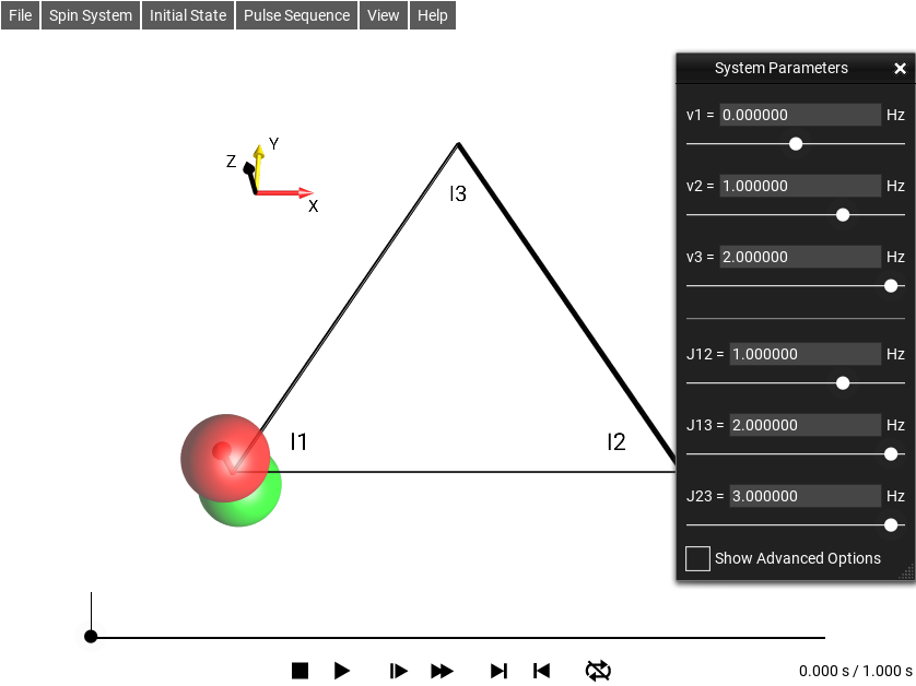
Fig. 7 The Spin System Parameter Edit Window
Selecting the Initial State
The initial state of the spin system is defined by choosing one of the options from the menu. The default initial state is \(I_{1z}\): z magnetization of the first spin.
In addition, the following commonly used initial states can be chosen:
\(I_{1x}\): x magnetization of the first spin,
\(I_{1}^{+}\) = \(I_{1x} + i I_{1y}\),
Total z magnetization (in the case of a three-spin system: , ie \(I_{1z}+I_{2z}+I_{3z}\)).
is a sub-menu with a selection of multiple-quantum operators with quantum order \(±p\) based on real combinations of Cartesian product operators.
is a sub-menu with a selection of multiple-quantum operators with a unique quantum order \(p\) based on raising and lowering operators.
The traceless part \((I_{1x}I_{2x}+I_{1y}I_{2y}+I_{1z}I_{2z})\) of the singlet state involving the first and second spin.
is a sub-menu with a few pure state operators.
These options open editors that allow you to change the initial density operator and to define any desired operator (see the following pages).
Multiple-Quantum Operators
The following options are available under the menu selection
: Zero-quantum operators involving the first and second spin.
, x component of the zero-quantum operator involving spins I1 and I2: \(I_{1x}I_{2x} + I_{1y}I_{2y}\)
, y-component of the zero-quantum operator involving spins I1 and I2: \(I_{1y}I_{2x} - I_{1x}I_{2y}\)
Zero-quantum operators involving three spins.
± 1-quantum coherence of the first spin (\(I_{1x}\), \(I_{1y}\))
and : ± 1-quantum operators of two and three spins, respectively.
and : ± 2-quantum operators.
: ±3-quantum operators involving three spins.
Note
In order to see how the current operator is defined in terms of Cartesian product operators, select . To inspect the initial Density Operator, make sure the time slider is set to 0.
Defined Coherence Order Using \(I^+\) and \(I^-\) Operators
The following options are available under the menu selection
Zero-quantum operators involving the first and second spin.
zero-quantum operator \(I_{1}^{+}I_{2}^{-}\) involving spins I1 and I2.
zero-quantum operator \(I_{1}^{-}I_{2}^{+}\) involving spins I1 and I2.
Zero-quantum operators involving three spins.
+1 or −1-quantum coherence of the first spin (\(I_{1}^{+}\), \(I_{1}^{-}\))
and : +1 or −1-quantum operators of two and three spins, respectively.
and +2 or −2-quantum operators.
±3-quantum operators.
Shorthand Notation for Cartesian Product Operators
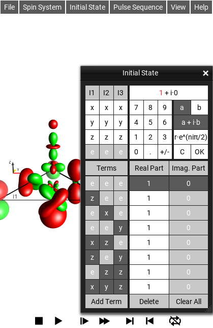
Fig. 8 The Initial State Editor
Selecting the menu opens the graphical Initial State editor. As seen under the column labeled Terms, the following shorthand notation is used for Cartesian product operators:
eee = 1/2 E,
zee = \(I_{1z}\),
exe = \(I_{2x}\),
eey = \(I_{3y}\),
xze = \(2I_{1x}I_{2z}\),
zey = \(2I_{1z}I_{3y}\),
ezz = \(2I_{2z}I_{3z}\),
xyz = \(4I_{1x}I_{2y}I_{3z}\)
Here, the letters “x”, “y” and “z” represent the individual Cartesian spin operators \(I_x\), \(I_y\) and \(I_z\) and the position of each letter indicates the spin it is associated with. The letter “e” represents the identity operator for a given spin. The standard prefactors are absorbed in this shorthand notation (“1/2” for the identity operator E, “1” for linear operators, “2” for bilinear terms, and “4” for trilinear terms). In order to emphasize the spin operators \(I_x\), \(I_y\) and \(I_z\), the letters “x”, “y” and “z” are displayed on a dark gray background, whereas the terms “e” are displayed with a light gray background in the list displayed on the right.
The Graphical Operator Editor
The initial state of the spin system can be defined in the input panel .
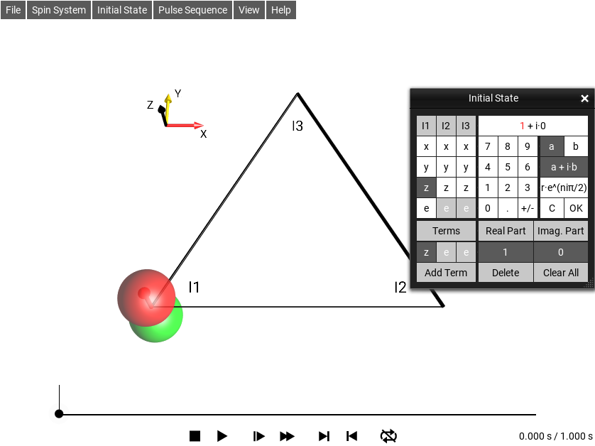
Fig. 9 The Graphical Initial State Editor Window
The example in Fig. 9 shows the input panel when opened with a current initial state of \(I_{1z}\) (i.e. zee in the boxes). The editor window is split into four parts, the top half is edit controls, and the bottom half is the list of the product operator’s terms.
In the upper left quadrant of the input panel, Cartesian product operator components can be selected using the buttons x, y, z, and e. The buttons appear in columns labeled I1, I2, and I3 corresponding to the first, second and third spin, respectively. The complex prefactor of the term currently being edited (\((1 + i·0)\) in Fig. 9) is shown in the display window at the top right. By default, the prefactors are displayed in the form \(a + i·b\), where \(a\) and \(b\) are the real and imaginary parts, respectively. Alternatively, the complex prefactors can be defined in terms of the radial part \(r\) and the phase \(φ=n·π\) by clicking the button r·exp(n·iπ).
For example, \(I_{1z}\) can be changed to \(I_{1x}\) by selecting x in the first column. Notice that the corresponding droplet in the DROPS display will instantly reflect this change.
The product operator terms of the initial density operator are listed in the the bottom part of the panel. In the example shown in Fig. 9, the initial state consists only of the term xee. The real and imaginary parts of the corresponding prefactor are 1 and 0, respectively, i.e. the first term is simply \(I_{1x}\).
Additional terms can be added by touching the button Add Term. By default, this creates the new term \((1 + i·0)·\) eee (short-hand notation for 1/2 the identity operator). In order to define the initial operator \(I_{1}^{+} = I_{1x} + i I_{1y}\), change the second term from eee to yee, and its prefactor from \((1 + i·0)\) to \((0 + i·1)\).
In order to change the prefactor \((1 + i·0)\) to \((0 + i·1)\), select the a + i·b mode, clear the real part a using the C button, activate the imaginary part by touching the b button and press 1. (Alternatively, you could activate the r·exp(n·iπ) mode and set n to 0.5).
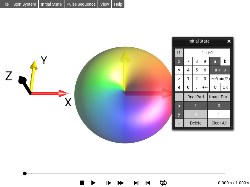
Fig. 10 Initial State \(I_{1}^{+} = I_{1x} + i \cdot I_{1y}\)
Now the initial density operator is set to \(I_{1x} + i I_{1y}\), with the first product operator term \((1 + i·0)·\) xee and the second term \((0 + i·1)·\) yee.
In the list of operator terms displayed in the bottom part of the window, you can activate and modify any desired term by a double tap. The real and imaginary parts of the prefactor of the activated term are highlighted by a white font on a dark gray background. The Cartesian product operator components and the prefactor of the activated term can be edited using the input panel. To remove the activated term, touch the Delete button.
For example, to change the operator \(I_{1x} + i I_{1y}\) defined on the previous page to \(-I_{1z} + i I_{1y}\), double tap the first term. This activates the first term and displays its current prefactor and product operator components in the input panel. Touch I1 : z, followed by +/- to change the first term from \(I_{1x}\) to \(-I_{1z}\).
Selecting a Pulse Sequence
The initial state of the spin system is manipulated by a pulse sequence, which can be selected from the menu. The current pulse sequence is displayed graphically at the bottom of the screen. In addition, you can display a listing of the pulse sequence elements (pulses, delays, isotropic mixing) by selecting or by double clicking on the displayed pulse sequence.
The default pulse sequence consists of a 90°y pulse followed by a free evolution period T having a duration of 100 milliseconds.
Basic Pulse Sequences
The following basic pulse sequences are available under the menu.
A 90° pulse with a desired phase (x, y, −x, or −y) can be chosen.
A 90° pulse with a desired phase (x, y, −x, or −y) can be chosen.
Here, z rotations of various angles can be chosen. These are obviously not directly realizable in an actual NMR experiment.
corresponding to a fixed delay of 1 second)
corresponding to a fixed delay of 1 second)
defines the duration of the delay in terms of the coupling constant J12 between the first and the second spin.
This has a number of sequences consisting of an echo sequence of a 90°y pulse (yellow) followed by a free evolution period T, a 180°x pulse (red), and a second period T:
An echo sequence with two 1 second delays during which the spin can dephase and rephase.
An echo sequence with a delay adjusted according to the current spin system’s J12 coupling time. This particular delay (\(1/(4*J12)\)) minimizes the magnetization remaining on the initial spin in a two-spin system.
In this menu, entries of a list of homonuclear and heteronuclear pulse sequences can be selected.
This menu contains a number of sequences to demonstrate Phase Cycling.
For convenience, pulse sequences for various tutorials, such as the Phase Cycling tutorial available in the download section can be found here.
This is where sequences created and saved by the user can be selected.
Note
See Color Code for the color code used in SpinDrops to represent pulse phases.
Homonuclear Pulse Sequences
has the following sequences:
For \(J12≠0\) and \(J13=J23=0\), this sequence of total duration \(1/(2 \cdot J12)\) transfers \(I_{1z}\) (i.e. z magnetization of the first spin) completely to antiphase coherence \(-2I_{1z}I_{2y}\).
For \(J12≠0\) and \(J13=J23=0\), this sequence of duration \(1/(2 \cdot J12)\) transfers \(I_{1z}\) (i.e. z magnetization of the first spin) completely to \(2I_{1y}I_{2x}\) (which is a mixture of 0- and ±2-quantum coherence).
This sequence consists of a period of selective isotropic mixing (of the first and the second spin) with a duration \(1/(2 \cdot J12)\), which transfers polarization \(I_{1z}\) via the zero-quantum term (\(I_{1x}I_{2y} - I_{1y}I_{2x}\)) to polarization \(I_{2z}\).
This sequence demonstrates a “round trip” polarization transfer of \(I_{1z}\) to \(I_{2z}\), to \(I_{3z}\), and back to \(I_{1z}\) using an I1-I2-selective isotropic mixing period of duration \(1/(2 \cdot J12)\), followed by an I2-I3-selective isotropic mixing period of duration \(1/(2 \cdot J23)\) and a final I1-I3-selective isotropic mixing period of duration \(1/(2 \cdot J13)\).
Heteronuclear Pulse Sequences
offers the following heteronuclear pulse sequences:
If \(J12≠0\), this sequence transfers \(I_{1z}\) completely to antiphase coherence \(2I_{1z}I_{2x}\), even if \(J13≠0\) and \(J23≠0\).
If \(J13≠0\), this sequence transfers \(I_{1z}\) completely to antiphase coherence \(2I_{1z}I_{3x}\), even if \(J12≠0\) and \(J23≠0\).
If \(J12≠0\), this refocused INEPT sequence transfers \(I_{1z}\) completely to \(I_{2x}\), even if \(J13≠0\) and \(J23≠0\).
If \(J13≠0\), this refocused INEPT sequence transfers \(I_{1z}\) completely to \(I_{3x}\), even if \(J12≠0\) and \(J23≠0\).
If \(J12≠0\) and \(J23≠0\), this sequence transfers \(I_{1z}\) completely to \(4I_{1z}I_{2z}I_{3z}\).
, ,
see Example 5: Spectral Editing for a detailed discussion of the DEPT sequences.
Phase Cycling Pulse Sequences
Todo
describe phase cycling demo pulse sequences
Tutorial Pulse Sequences
Todo
describe tutorial pulse sequences
New Sequence
Additional homonuclear or heteronuclear pulse sequences not contained in the list of predefined sequences can be created using the sequence editing tools, which are described in more detail in Sequence Editor.
To create a new sequence, select an existing sequence of the type you want to create (either Heteronuclear or Homonuclear), and save it with a new name. This new sequence will appear in the menus under .
With the sequence editing tools described in Sequence Editor it is possible to modify existing pulse sequences. To edit a given pulse sequence simply double-tap the graphical pulse sequence display, or select the menu item . Within the editor, sequence elements can be modified, copied, pasted, dragged, deleted and created.
Controlling the Simulation
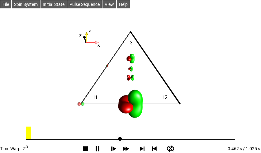
Fig. 11 \(\rho_0 = I_{1z}\)
The buttons below the pulse sequence interactively control the simulation of the spin dynamics:
Stop and return to the beginning of the pulse sequence
/
Play/Pause
/
Slower/Faster
/
Skip to the end/beginning of the current pulse or delay
/
Repeat mode off/Repeat mode on
When there is enough space on the screen, the current time (here = 0.462 s) and the total duration of the pulse sequence (here = 1.025 s) are displayed to the right of the control buttons.
When a simulation is running, the acceleration factor (Time Warp) is displayed at the left of the control buttons, when there is enough space on the screen. For example, an acceleration factor of \(2^{-3}\) indicates that the simulation is slowed by a factor of \(2^{-3} = 1/{2^3} = 1/8\). Touching the Slower or Faster button halves or doubles the acceleration factor.
Controlling the Simulation Time
The dot and the attached vertical line indicate the current time point of the simulation. As explained in the previous section, the current time point can be controlled using the control buttons at the bottom of the sequence plot.
It is also possible to control the time evolution directly by dragging the white dot to the desired position.
This allows you to precisely control the speed with which the DROPS display is changed during the pulse sequence.
Manipulating the DROPS Display
To view the three-dimensional shapes of the droplets from different perspectives, you can rotate, shift and zoom the DROPS display with one- or two-finger gestures (as illustrated on the following pages). In the desktop versions of SpinDrops, additional keyboard commands are available to change the viewing position and frame.
A double click will restore the default view of the DROPS representation. This “default view” position for the current spin system size can be set by selecting the menu item .
Coordinate System
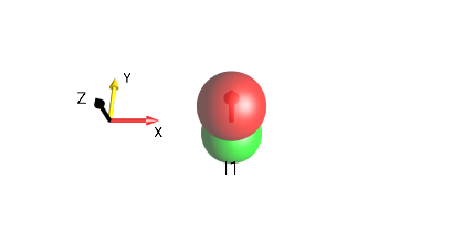
Fig. 12 \(I_{1z}\)
In the DROPS display, a coordinate system is usually shown for reference. The axes of the coordinate system are labeled x, y, and z and in addition, the following colors are used to easily distinguish the axes:
x axis: Red
y axis: Yellow
z axis: The current Foreground text color (here it’s Black)
Layouts
Three-Spin Triangle
In the standard DROPS display based on the LISA Basis, the location of a droplet indicates the set of involved spins. The following locations are used in the default setting:
Droplets corresponding to product operator terms involving only a single spin operator (linear terms) are located at the corners of a triangle. Each corner is labeled to indicate its spin (I1, I2, or I3) association.
Droplets corresponding to bilinear terms are located on the corresponding edges of the triangle.
Droplets corresponding to trilinear terms are located in the center and above the triangle.
The droplet representing a term which involves no spin operator (i.e. which is proportional to the identity operator) is located below the triangle.
An example of the DROPS display, including linear, bilinear and trilinear terms and the identity operator, is shown in (Fig. 13).
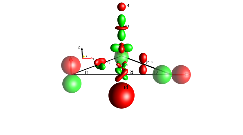
Fig. 13 \(I_{1x}I_{3y}+I_{2z}I_{3z}+I_{1x}I_{2z}+4I_{1x}I_{2y}I_{3z}+I_{1z}+I_{2x}+I_{3y}+0.5 \cdot Id\)
This table shows a breakdown of all the droplets by their spin-involvement (linearity) classification.
bilinear terms 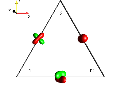
Fig. 14 \(I_{1x}I_{3y}+I_{2z}I_{3z}+I_{1x}I_{2z}\)¶ |
trilinear terms 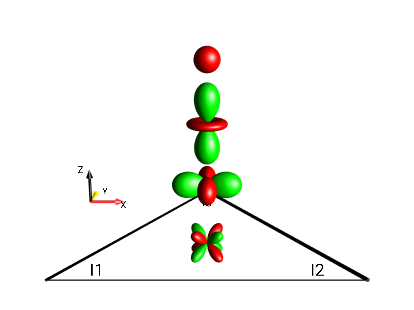
Fig. 15 \(4I_{1x}I_{2y}I_{3z}\)¶ |
linear terms 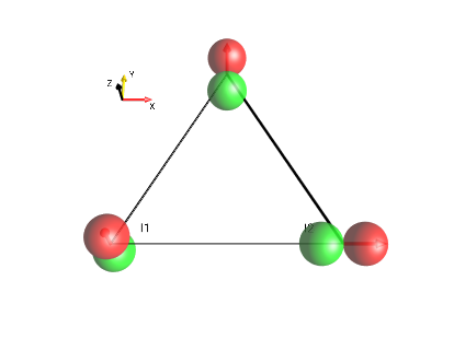
Fig. 16 \(I_{1z}+I_{2x}+I_{3y}\)¶ |
identity operator 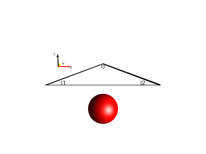
Fig. 17 \(0.5 \cdot Id\)¶ |
In the standard DROPS display, these terms are shown simultaneously in one figure, as in Fig. 18.
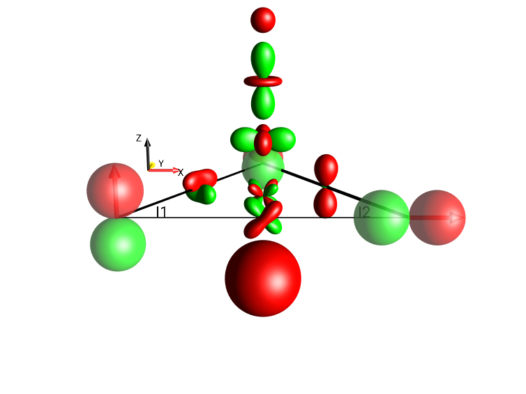
Fig. 18 \(I_{1x}I_{3y}+I_{2z}I_{3z}+I_{1x}I_{2z}+4I_{1x}I_{2y}I_{3z}+I_{1z}+I_{2x}+I_{3y}+0.5 \cdot Id\)
Three-Spin Chain
For three-spin systems with, the droplets representing linear terms can also be positioned on a line (rather than at the corners of a triangle) by selecting the menu . The locations of the bilinear and trilinear terms are schematically indicated in Fig. 19.
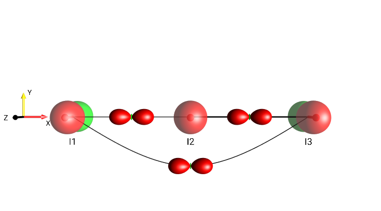
Fig. 19 Three-Spin Chain Layout
Two Spins
For systems consisting of two spins, the DROPS display can be adapted by selecting . The locations of the linear terms and the bilinear term are schematically indicated in Fig. 20.
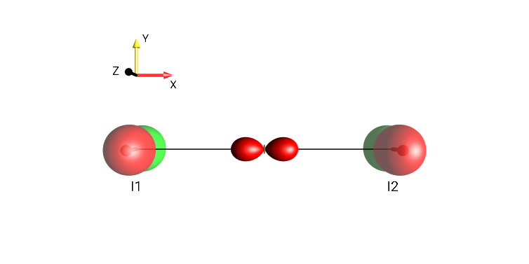
Fig. 20 \(I_{1z}+I_{1x}I_{2x}+I_{2z}\)
Two Spins, dissection
bilinear terms 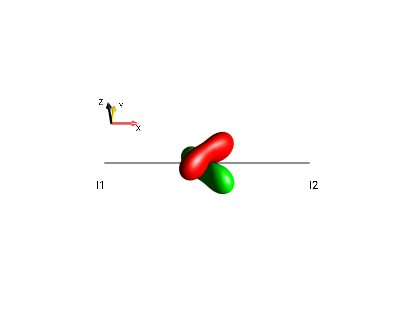
Fig. 21 \(2I_{1x}I_{2y}\)¶ |
identity operator 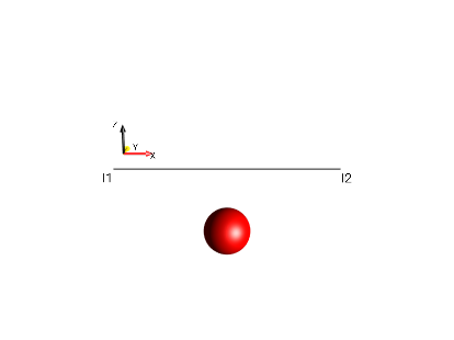
Fig. 22 \(0.5 \cdot Id\)¶ |
linear terms 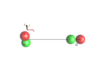
Fig. 23 \(I_{1z}+I_{2x}\)¶ |
all terms 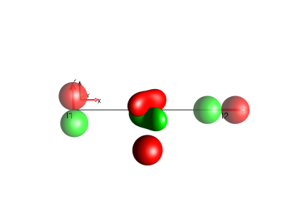
Fig. 24 \(I_{1z}+0.5 \cdot Id+2I_{1x}I_{2y}+I_{2x}\)¶ |
A Single Spin
For systems consisting of a single spin, the DROPS display can be adapted by selecting . When the preference setting Show Id Droplet is enabled, the term proportional to the identity operator is located below the linear term.
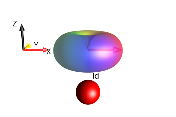
Fig. 25 \(I_{1}^{+}+0.5 \cdot Id\)
Separation Types
The menu allows selection of several alternative advanced DROPS display modes beyond the default Three-Spin Triangle DROPS display. In particular, it is possible to partition the compact standard droplets in terms of coherence order \(p\) and/or rank \(j\).
Droplet Separation
To see the coherence orders and tensor ranks contained in a given state, the standard droplets can be split into sub-droplets according to the following Separation options:
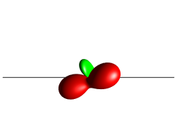
No separation, Standard Layout
No separation, Standard Plane
These different separation modes are illustrated in the following sections.
Standard Layout
This is the default 3-spin layout, the linear terms are laid out in the x-y plane, the bilinear terms are on the same plane between the linear terms, and the trilinear terms are on a line extending from the center of the triangle “up” along the z-direction; Fig. 26 demonstrates this with a single bilinear droplet along with a number of trilinear terms stacked toward the viewer. This view mode can be selected under the menu .
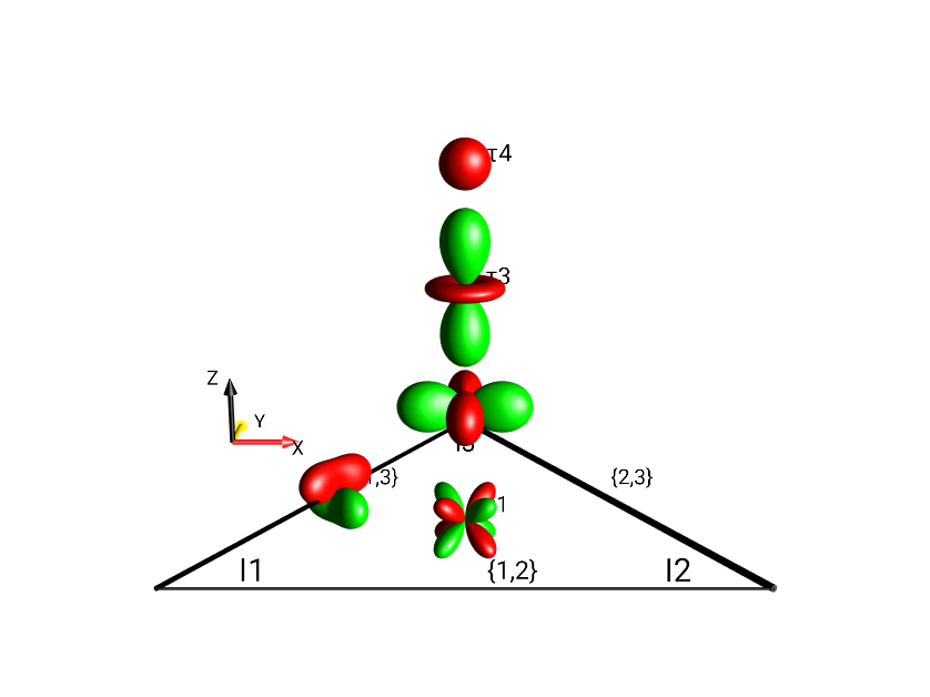
Fig. 26 \(4I_{1x}I_{2}^{-}I_{3z} + I_{1x}I_{2y}\) in Standard Layout, No Separation
Standard Plane
In Standard Plane mode, the same droplets are used as in Standard Layout mode, but the droplets – particularly the trilinear terms – are moved to a single plane (in preparation for the other separation modes which use the z-direction to indicate coherence order). Fig. 27 shows the same operator as Fig. 26 (\(4I_{1x}I_{2}^{-}I_{3z} + I_{1x}I_{2y}\)) using the mode.
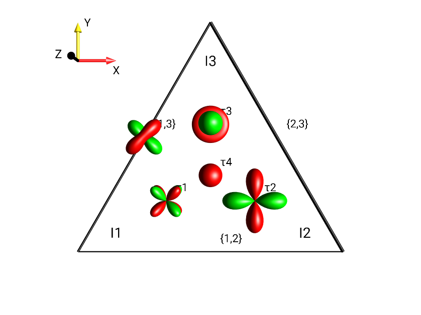
Fig. 27 \(4I_{1x}I_{2}^{-}I_{3z} + I_{1x}I_{2y}\) in Standard Plane, No Separation
Separation Based on Coherence Order \(p\)
Schematic representation of droplet locations in multiple planes based on Coherence Order for a three-spin system. Fig. 28 displays labels indicating the coherence order \(p\) at every droplet location. This view mode can be selected under the menu .
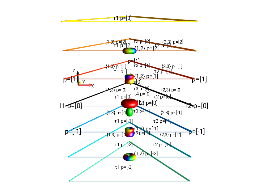
Fig. 28 Separation by Coherence Order of \(I_{1x}I_{2x} + I_{1x}I_{2y} + I_{1x}I_{2z}\).
Separation Based on Absolute Value of Coherence Order \(|p|\)
A more compact representation of coherence order \(p\) separation, limited to the absolute value of coherence orders is shown in Fig. 29. The layout is essentially the same as Fig. 28, but only extends in the positive z-direction. This view mode can be selected under the menu .
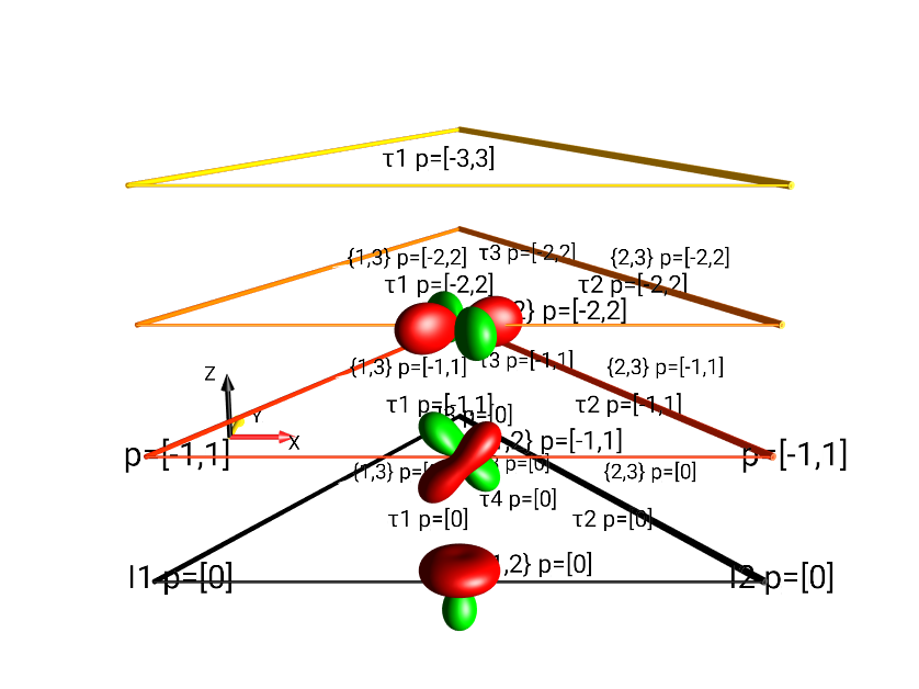
Fig. 29 Separation by \(|p|\) of \(I_{1x}I_{2x} + I_{1x}I_{2y} + I_{1x}I_{2z}\).
Separation Based on Tensor Rank \(j\)
Extending outward from the locations of the droplets in the Standard Plane representation, the display mode shown in Fig. 30 separates droplets according to their rank (see details about LISA’s Tensor Groups for 3-spin system), adding up to 11 droplets in the x-y plane. This view mode can be selected under the menu .
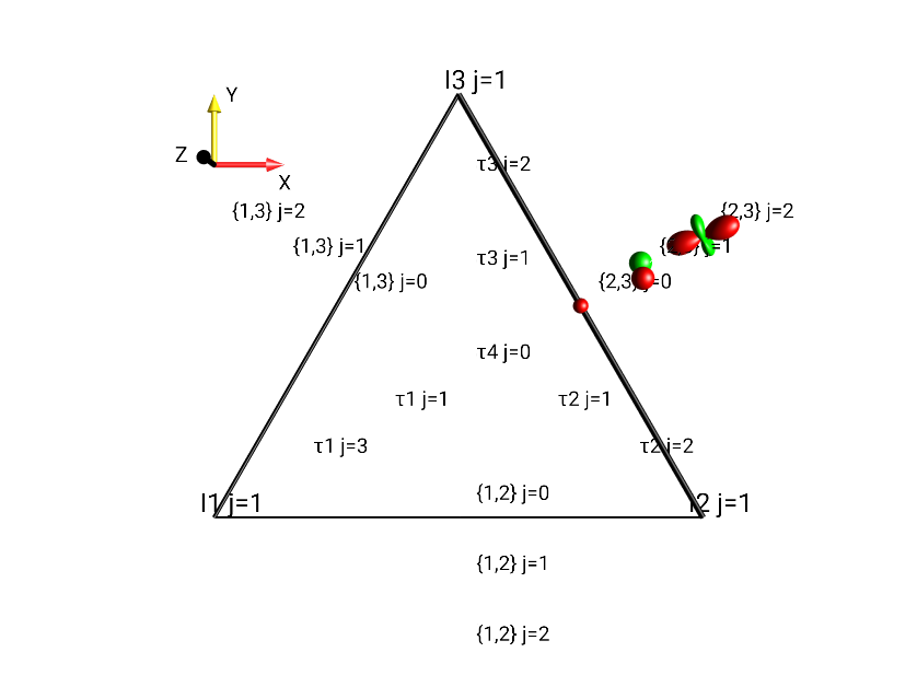
Fig. 30 Separation by Tensor Rank \(j\) of \(0.5 \cdot (I_{2x}I_{3x} + I_{2x}I_{3y} + I_{2x}I_{3z})\).
Separation by \(j, |p|\)
In the j, |p| representation, the standard droplets are split and separated based on both rank \(j\) and the absolute value \(|p|\) of coherence order. (For more details on the rank of operators, see the section Tensor Grouping in the LISA basis). The coherence orders are limited to the range \(0 ≤ |p| ≤ j\). For example, the droplet “\(\{1,2\}\)”, representing bilinear operators involving spins I1 and I2 contains tensors of rank \(j=0\) with \(|p|=0\), tensors with rank \(j=1\) with \(|p|∈ \{0, 1\}\), and tensors with rank \(j=2\) with \(|p| ∈ \{0,1,2\}\). This view mode can be selected under the menu .
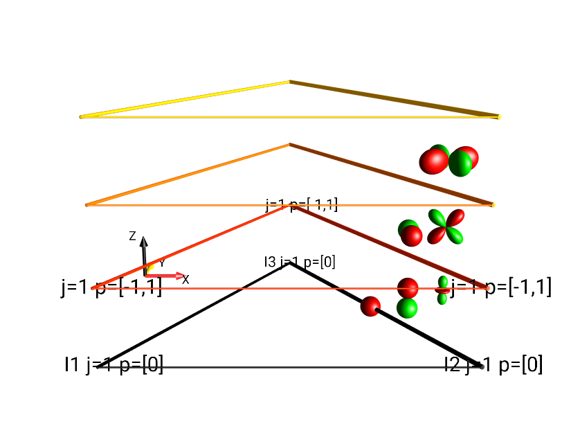
Fig. 31 Separation by Tensor Rank \(j\) and Absolute Value of the Coherence Order \(|p|\) of \(I_{2x}I_{3x} + I_{2x}I_{3y} + I_{2x}I_{3z}\).
Separation type \(j, p\)
Seen in Fig. 32 is the most finely-separated view mode, it separates all droplets according to both rank and coherence order. This view mode can be selected under the menu .
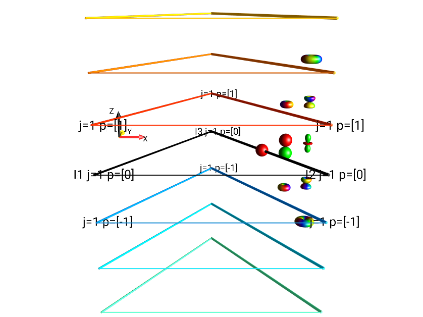
Fig. 32 Separation by Tensor Rank \(j\) and Coherence Order \(p\) of \(I_{2x}I_{3x} + I_{2x}I_{3y} + I_{2x}I_{3z}\).
Multiple Projects
It is possible to create multiple projects within SpinDrops. Each project contains an entirely separate simulation and experiment. Saved pulse sequences are available from any project.
A project uniquely contains:
the spin system and its parameters,
the simulation parameters,
the default views and separation used in the DROPS display,
the colors for the SpinDrops display,
the initial state,
the pulse sequence.
New projects can be created with the Save Project As… menu selection. To switch to a different workspace, select the workspace from under the Open Project menu.
Projects can be imported and exported from SpinDrops for sharing with other SpinDrops users, or backing up a copy outside of SpinDrops.